
I made a photo frame built on an ESP32 with an E-Paper display. The picture shown in the frame can be changed from a smartphone over a web interface. I decided to call it “PaperFrame”
All started after a professionnal project I did with a three colours e-paper display. I was able to drive the display and changing images on it, but I never found a usecase for it. Then the idea came ! I don’t pretend to be the only one to have built this idea, but here is my interpretation of it.
What is an E-Paper display ?
I won’t do the job better than Wikipedia. But the things to retain about the Electronic Paper are the following:
- Only a few colors (black, white and red in my case)
- Low framerate
- Looks like paper
- No light/sun reflect
- Consumes energy only when refreshing the frame
- No need for backlight
For a photo frame, it’s a perfect fit thanks to the low power consumption: we don’t really want to keep it plugged to the mains, or to drain a battery in a few hours. The downside is the reduced number of colors that can be used. The picture isn’t either shown as the original if it’s not black and white.
Bill of materials
For this project, I used only existing modules from Waveshare and some spare parts from my drawers.
- 7.5inch E-Paper (B) E-Ink from Waveshare
- black/white/red colors
- 480x800px resolution
- Universal e-Paper Raw Panel Driver Board from Waveshare too
- ESP32 MCU from Espressif
- 4MB ROM & 512kB RAM
- WiFi and BLE capabilities
- 3.3v or 5v power
- E-Paper driving circuit included
- 3x AA battery handler
- Provides 4.5v, enough to make it work
- Any 13x18cm photo frame you like
Software
All the MCU software is written in C, based on the excellent ESP-IDF. To avoid all the IDF installation, I used a devcontainer on VSCode, thanks to this guy! On the Web side, I used the standard trio HTML5/CSS3/JavaSript.
The concept is quite simple. When powered-on or reseted, the ESP32 starts a WiFi access point that the smartphone will connect to. When accessing the url http://paperframe.io, the web interface is shown to the user. On this interface, the user first uploads an image. The image is then converted to black white and red before being sent to the MCU. The MCU then initializes the E-Paper display, sends the framebuffer to it and the display then is sent to deep sleep to minimize its power consumption. After this’ the ESP32 gets itself to deep-sleep to save power. The only way to restart this process is to reset it with the physical button. If nothing happens in the two minutes following the device power-up, it goes to deep-sleep again. The flowchart below summarizes this.
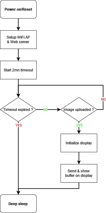
After use, I think it would be better to shutdown the MCU only after the WiFi is disconnected. This would allow the user to replace the picture several times if the result is not satisfying, without reconnecting to the access point.
Image processing
The image taken from a camera is very different from the one an E-Paper display needs. My display needs a 480×800 pixels frame, with colors encoded on 2 bits (black/white and red/non-red). As the input image can be very large, it’s difficult to send it entirely to the ESP32 to process it. Then I decided to process the image in the browser, with some Javascript code.
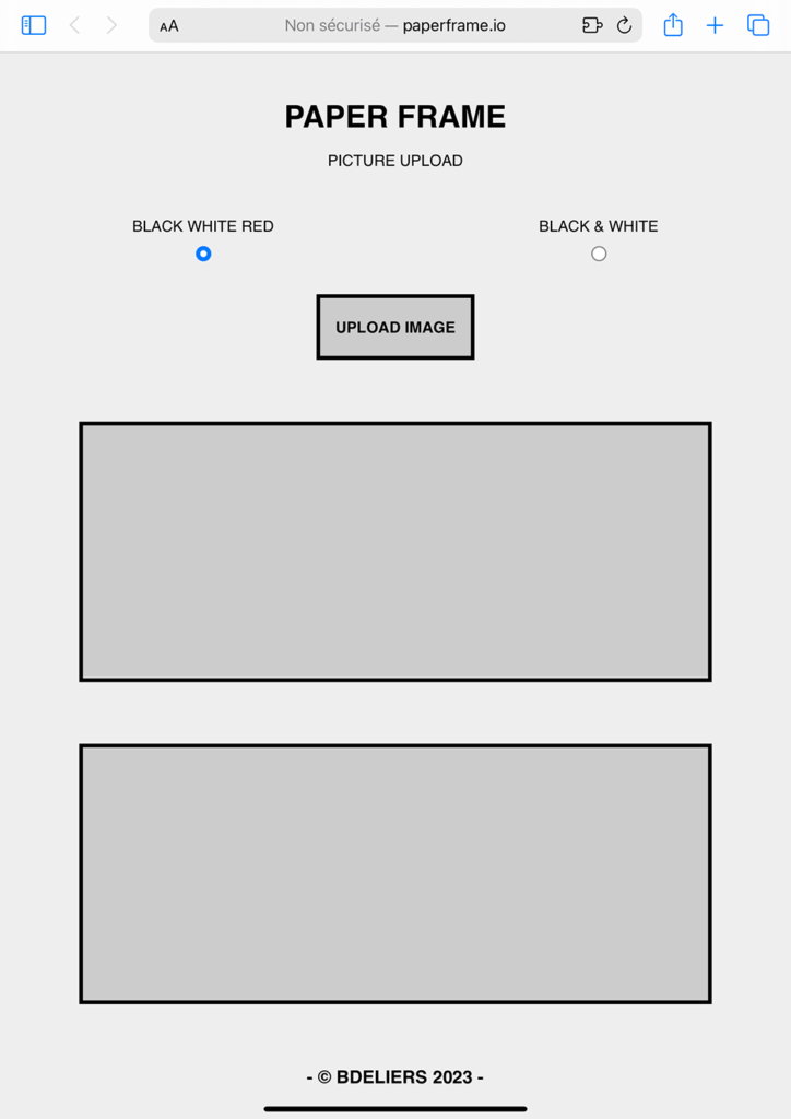
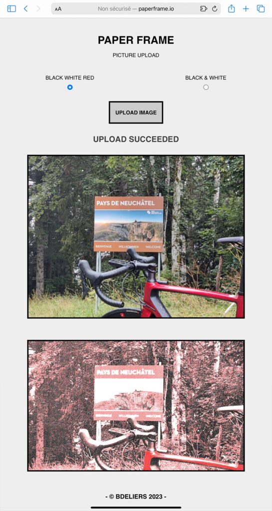
The interface in itself is very basic as it needs just a button to trigger the image choice and two zones to show the picture before and after it was processed. I finally added radio buttons to enable the black&white mode. The general design very simple and is kind of “neo-brutalism“. It was easy to make it responsive thanks to the flexbox layout of CSS. This very simple layout has a very small footprint in the ESP32’s ROM and is fast to load in the browser.
First the image is rotated to landscape format if it’s higher than larger. The script crops it to a 5:3 ratio as on the display then downsizes it to a width of 800 pixels. Now that the image has the right size, the last step is to convert it to our very reduced colorspace. To do so, I used the Floyd-Steinberg dithering algorithm after the quantization process to have a nice result. The principle of this dithering method is to distribute the color-quantization error to the neighbours of each pixel to make the transitions smoother than just clipping the pixels to the nearest color.
Quantization and dithering process
For each pixel, we take the modulus of the color components and interpret it as an illuminance ratio between 0 and 255 as the red green and blue channels of each pixel are encoded on a byte.

Then, the red and black/white values are compared with the illuminance to the decide the pixel’s color.


Last step is to distribute the quantization error to the neighbours of the pixel. Error is first computed as follows.


Finally the errors are added to the not yet quantized right, bottom-left, bottom and bottom-right pixels of the image.

Below you can see the interface before an image is sent by the user then after an image was sent and processed.
All the software is available under Apache-2 license on my gitHub.
The result !
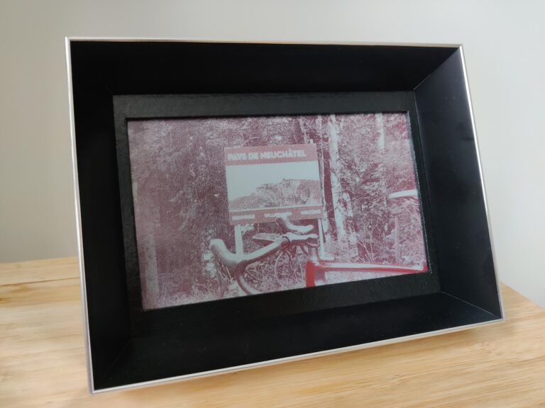
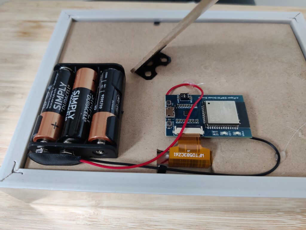
Now that the hardware was loose on my desk and the software ready, time came to assemble it into a nice frame. I used a standard frame for 13x18cm pictures from which I replaced the glass by the display. Then I had to make a small hole in the wooden backplate to take the display’s tail out and connect it to the driver board.
I glued the driver board and the batteries socket on the back with a hot glue gun. You can see the result below.

As you can imagine, the person I gifted this for chistmas was as impressed as all the people who seen it. For the future, I plan to make a PCB myself to integrate everything easily and avoid the flying wires. I would also like to make on with a Polaroid format, and why not making it commercial !